Balancing a ball on a table in a desired position is one of the most important and classical problems of control theory. Altair, partnering with ACROME, promotes the unique experience of a digital twin mechatronics simulation and hands-on experiment platform to teach and learn model-based controller design concepts with a 3D+lD system co-simulation engine.
The Ball Balancing Table (BBT) is a well-known kit for all mechatronics enthusiasts. Even if it might appear quite simple, it allows to investigate many aspects of control, for example anti-windup scheme for PID control.
The Ball Balancing Table (BBT) is a well-known kit for all mechatronics enthusiasts. Even if it might appear quite simple, it allows to investigate many aspects of control, for example anti-windup scheme for PID control.
Explore MoreSales Enquiry
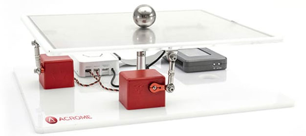
The main parts of the BBT kit are:
The main parts of the BBT kit are:
- Power Supply
- Controller (Arduino)
- RC Servos
- 2D resistive touch screen
- Steel Ball
| Features | |
|---|---|
| Assembled and ready to control plant with the integrated power unit. | Getting Started Program with rich Graphical User Interface for out-of-the-box user experience |
| Implementation of advanced digital control techniques | Fully compatible with Altair Activate |
| Fully documented system models and parameters provided for Altair Activate. | Ball position feedback using a high precision touch surface (camera based feedback optional) Actuating the table by RC servo motors, which are familiar to students. |
| Rectangular and circular path options are integrated in the software. | Enables students to create their own real-time algorithms. Open architecture with extensive courseware, suitable for undergraduate courses for engineering disciplines related to control systems. |

Teachers
Prepare your students to hit-the-ground-running in their work as mechatronics engineers!

Students
Get the premier mechatronics jobs! As an explorer, empower yourself with the next generation engineering tools to innovate better and faster.
| STARTER KIT | EXPANSION KIT |
|---|---|
| Hardware+ Courseware | Hardware+ Courseware |
| Teaching License of Software | |
| Initial Setup Help and Training (via web) |
- Only l Starter Kit is needed. If you already have the Altair software, you need only purchase Expansion Kits.
- Software License includes: Altair Compose®, Altair Activate®, Altair MotionSolve™ & MotionView™.
- All software apps can be installed and run on student computers and/or on school computers.
| Features | |||
|---|---|---|---|
| Components of Ball Balancing Table | Fundamentals of PWM |
System Modelling |
Feedback in Control Systems |
| RC Servo Motors | PWM Signaling Theory | Lagrangian Method | Reading Ball Position from Touch Sensor |
| Touch Sensor | Generating PWM Signals Driving RC Servos with PWM Signals | Newton’s Law of Motion | Derivative Filtering |
| Controller | Modeling of Actuator | ||
| Acrome Power Distribution BoxMechanics of the System | Obtaining Transfer Function | ||
| Performance Measure |
Control System Design |
Control System Verification | |
| Time Domain Characteristics | Design of Linear Controllers | Frequency response analysis | |
| Steady State Response and Steady State Error | PID controller and Fuzzy Logic Controller | Experimental Bode Diagram | |
| Comparing the Simulation and Real System Responses for Different Controllers | Cut-Off Frequency Determination | ||
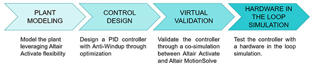
The following is the typical workflow for a typical BBT experiment
The closed loop system can be easily modeled in Altair Activate through this block diagram:
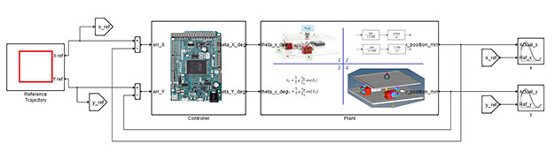
The last step is to test and validate the controller with the real BBT kit. This means that we are performing a hardware in the loop simulation.
As you can see the digital twin and the real BBT kit behave almost the same: